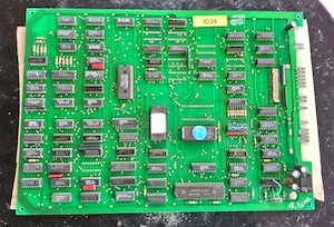
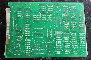
Pac-man Repair & Troubleshooting Guide
Content originally created by Lawnmowerman

This resource is maintained in part by the community. Have information to add or items to change? Drop me a line.
Check out the Ms. Pac-man arcade game page for more resources specific to that machine.
Pac-man Information and Resource Links
Pac-man Settings
Pac-man Dip Switches
| SW #1 | SW #2 | SW #3 | SW #4 | SW #5 | SW #6 | SW #7 | SW #8 | |
| Free Play | ON | ON | ||||||
| 1 Coin 1 Play | OFF | ON | ||||||
| 1 Coin 2 Plays | ON | OFF | ||||||
| 2 Coins 1 Play | OFF | OFF | ||||||
| 1 Pac Man | ON | ON | ||||||
| 2 Pac Men | OFF | ON | ||||||
| 3 Pac Men | ON | OFF | ||||||
| 5 Pac Men | OFF | OFF | ||||||
| Bonus Pac-Man @ 10K | ON | ON | ||||||
| Bonus Pac Man @ 15K | OFF | ON | ||||||
| Bonus Pac Man @ 20K | ON | OFF | ||||||
| No Bonus | OFF | OFF | ||||||
| Rack Advance | ON | OFF | ||||||
| Freeze Video (pause) | OFF | ON | ||||||
| Game Operates Normally | OFF | OFF |
Notice: The bonus settings vary according to software variants.
Pac-man Pinouts
 |
|||||
| Parts Side | Wire Color | Solder Side | Wire Color | ||
| 7 Volt Center Tap (GND) | Red-Black | A | 1 | 7 Volt Center Tap (GND) | Red-Black |
| 7 Volt Center Tap (GND) | Red-Black | B | 2 | 7 Volt Center Tap (GND) | Red-Black |
| 7 Volt AC | Orange | C | 3 | 7 Volt AC | Orange |
| 7 Volt AC | Green | D | 4 | 7 Volt AC | Green |
| E | 5 | Coin Multiplier PCB | Blue-Red | ||
| Speaker + | Green Brown | F | 6 | Reset Credit Multiplier | White-Brown |
| Speaker - | Red-Yellow | H | 7 | ||
| Coin | Orange-Green | J | 8 | ||
| Tilt | Orange-White | K | 9 | Credit Switch | Red-Green |
| One Player Start | Brown-Black | L | 10 | Two Player Start | Black-Yellow |
| One Player Left | Blue-White | M | 11 | One Player Right | Yellow-Red |
| One Player Up | White-Red | N | 12 | Two Player Up | |
| Two Player Left | P | 13 | Two Player Right | ||
| Cocktail Table Mode | R | 14 | One Player Down | Brown-White | |
| Video Ground | Green-Red | S | 15 | Ground for Player One | Red |
| Video Red | Red-White | T | 16 | Video Green | White-Brown |
| Video Blue | Yellow-Black | U | 17 | Video Sync (Negative) | Orange-Red |
| Two Player Down | V | 18 | +5 VDC Coin Multiplier PCB | White-Orange | |
| 12 Volt AC | Black-White | W | 19 | 12 Volt AC | Black-White |
| 12 Volt AC | Blue-Yellow | X | 20 | 12 Volt AC | Blue-Yellow |
| 12 Volt Center Tap (GND) | Yellow-Green | Y | 21 | 12 Volt Center Tap (GND) | Yellow-Green |
| 12 Volt Center Tap (GND) | Yellow-Green | Z | 22 | 12 Volt Center Tap (GND) | Yellow-Green |
Note: The edge connector in the photo on the left is a bit dirty. The larger pads at 1,2 (A,B) & 21,22 (Y,Z) often times become burnt from dirt/ resistance and require rebuilding of PCB edge & wiring harness or as often done by operators, "creative rewiring", where wires are taken from the wiring harness and soldered directly to the PCB bypassing the connector.
Basic Pac-man Board Tips
All Ms Pac Man printed circuit boards are actually Pac Man circuit boards that have had a auxiliary board plugged into the original location of the Z80 CPU and the 2 character chips at 5E, 5F changed to Ms Pac chips.
- First troubleshooting tip for Ms. Pac boards is to remove the ribbon cable/auxiliary board from the main PCB and then transfer or better yet install a known good Z80 into the CPU socket. If the Ms. Pac-man now runs but exhibits odd characters you know that either the ribbon cable or some component on the auxiliary board is deffective. (The card can be eliminated, read on....)
- Check the piggyback boards at 5S and 6D to be securely seated. (More on the Piggyback Boards)
- Check dip switch #8 to be OFF
- Check slam switch on coin door to be normally open.
- Cocktail boards are identical to uprights, to enable cocktail mode edge connector pin R is grounded.
Pac-man Board is Dead
Replace 74LS74 @ 8C.
Signs of Life
No Vertical Sync - lines and colored block out of sync. No game play.
Replace 2R & 2S (74LS161)
Red Screen on Maze portion only, HI Score & Credits legible
Short on Ram Chip @ 2D.
HI Score & Credits legible, no Maze or graphics. Shorting 3E pin 6 to pin 7 shows maze but no sprites.
Bad 93415 RAM pulling Chips Select down.
6 Moving blocks of scrambled garbage
Replace 74LS74 @ 3N, output pins 5 & 6 bad.
Flashing A in upper right & Flashing "2" in Lower left
Pin 1 of 6H out of socket
2-3 Characters in upper left - seems locked up
Check 74LS74 @ 8C for lifted pin 11 used in speed up mods
Maze has white bar running top to bottom. Maze is okay but has sections of white instead of blue. "TOP SCORE" & other letters change color on demo screen as new characters enter.
Replace 2114 Rams & check sockets.
Powers Up but as characters come on screen it resets.
Bootleg Ms Pac - Rom 5 is Bad.
Checkerboard / Picnic Table pattern, Test Grid looks like "L"s
74LS139 @ 5C outputs 9, 11, 12 bad.
Seems locked up but will occasionally start if you keep toggling it off and on. Reset button on board will not work.
Replace 74LS161 @ 9C.
Game resets often, and/or won't boot. (Also causes Clay's Multi-Pac to reset to menu and freeze)
Chip 8B, 74LS368, inspect for cold solder joints or corrosion on pins. (Thanks Jeff)
Constant Reset, Shorting Z80 pin 34 to pin 35 will force boot but with corrupt graphics. (PAC 3 board)
2114 Ram at 4M bad (4P on real board).
Game will only run with custom Sync Bus Controller chip, not with TTL equivalent.
74LS161 @ 3R has poor connection pin 7, effects 2H signal.
Horizontal white lines, can see Marquee lights on intro screen & can see "trail" of Ms Pac in Maze.
74LS174 @ 1H pin 9 open.
Switch / Coin / Inputs fail to register or clear
logicprobe.html Half way down is the section devoted to troubleshooting inputs.
Garbage, RAM test dies at $4080, AB7 appears good.
74LS138 @ 7J interfering with good reads from RAMs. (3/24/02)
Plays But....
Plays, Garbage on screen.... U H S A T B T O (push button to play text)
Replace V-ram address board ( 284)
Plays, 4 Ghost & Pac Man in Maze.
Replace 74LS20 @ 3E (bad output).
Plays, Images and Text are 4 1/4 of the left side of a Sprite repeated.
Bad 74LS283 @ 1F (pins 9, 10, 13).
Plays, Images are 4 1/4 of the left side of a Sprite repeated. Placed slightly to left of Marquee box (Ms Pac). Motion & Demo are jerky.
Bad 74LS283 @ 1E (pins 1, 9, 10).
Plays, but Text (GAME OVER) is split in half horizontally & wrapped around.
74LS86 @ 4E, pin 5 bad.
Plays, 2 parts of moving objects.
Replace 74LS283 @ 2F (bad output).
Plays, but moving objects are 2 copies of left half.
Replace 74LS157 @ 4D (4E), pin 7 bad.
Plays, 2 copies of moving Sprites on Attract Screen, MS Pac is 2 halves, (Red, Blue Orange Ghost are halves too before game starts).
Bad 74LS283 @ 2F (pin 10 high only).
Plays, Green running dashed lines on the screen otherwise okay.
Replace 74LS75 @ 3D.
Plays but screen is covered with white "snow". Heat related, not Video RAMs (2A~2D), Character ROMs or Scratchpad RAMs (4K~4R).
Replaced 74LS75 @ 3D.
Plays but Constant Chattering/ Static Noise, Sprites are corrupt. Maze has 2-3 bands of erratic displays.
Bad output on pins 5, 6 of 74LS74 @ U4 of Sync Bus Controller.
Plays, Men & Pac Man too high in Maze by 2-3 Characters
Pins on Ram @ 2A shorted to each other.
Plays, Pac Man too high in Maze, jumps about vertically.
74LS161 @ 2E bad outputs. (Thanks Chuck)
Plays, Double Vision, 2 mazes side by side.
Replace 74LS74 @ 5M, no output on pin 9
Plays, Characters are odd blobs in game but correct on demo screen static pictures Also motion is wrong - demo screen characters move diagonally
Pin 8 of 5S (Vertical Ram Addresser 284) is out of socket
Plays, MS Pac running light marquee is numbers & Midway Logo is parts of Speedy.
Roms 5E & 5F are Pac Man not Ms Pac Man Roms.
Plays, but graphics colors are wrong.
Bipolar Proms at 4A & 7F are wrong/bad (see check sums page).
Plays, but Orange Pac-Man on the playfield and the cyan/pink ghosts.
Replace 2A 93415 RAM. (from RGVAC newsgroup).
Plays, But Sue runs out of maze & erratically jumps about.
Replace Rom @ 6F (Speed-Up Bad).
Plays, But sync needs to be readjusted and bottom of maze is off screen, under the credit display.
Replace 74LS161 @ 3S (Signature shows problem).
Plays, But speed & sound erratically change & game may occassionaly crash.
Bad 74LS249 @ 9N (bootleg board).
Plays, But all moving characters are at the bottom of the screen moving left/right only.
Replace 74LS377 @ 4B. (Output pin 6 was bad)
Plays, But all character movements horizontally (left/right & vice versa) are jerky (Vertically okay).
Pin 15 @ 1F (74LS283) out of circuit.
Plays, But Vertical "Hum Bar" (Scrolling black/dark line on monitor about 1 inch wide.)
See the Vertical Bam Hum area under the Power Supply section.
Plays, No Characters in Maze or intro Screen. Dots visible & disappear as eaten.
(rare case) Dead 74LS157 at U5 of V-Ram Addresser (rare case).
Plays, 2 Sets of Characters in Maze, Large blank stripe down the left side of the screen from top to bottom, Characters in wrong places but dots disappear correctly.
64V missing from 2F 74LS283 pin 14.
Plays, But Maze graphics are wrong/ corrupt. Full of large segment of "super Pac Man" from intermission.
No HBLANK signal to pin 4 of 74LS174 @ 1H. (Traced back from graphics roms chip selects)
Plays, But Ghost, Maze & Pac are Corrupt.
4D pin 2 bad.
Plays, But corrupt graphics blocks (See http://www.seanet.com/~wilson/arcade/pacman.html)
Replaced 74LS174 @ 1H.
Plays but No Red on moving sprites (Ms Pac Bow/ Cherry/ Speedy).
Ram Data Bus D5 high resistance.
Plays, But Maze graphics from the bottom half are displayed on the top half also. Characters follow the original maze patterns.
Replaced 74LS257 @ U2 on VRam addresser board (Thanks Fred!)
Coins up but joystick only moves Pac-Man down. Rack Advance (dip switch 7) doesn't work.
Pin 15 of 8E is out of circuit (Thanks Mark Hooks!)
Plays, but Pac/Ms. Pac and all the monsters go through the maze upside-down! All other graphics are okay. Pac and the monsters look like they're upside down.
Bad 74LS157 at location 4E, pin 9. This chip is a quad, dual-input multiplexer. The "FLIP" signal, activated when the board is in cocktail mode, flips over all video signals during Player Two and this chip was not selecting its inputs correctly. "FLIP" was getting through in this channel when it should not have been. Replacing this chip cured the problem. (Thanks Matt McCullar)
Other Specific Problems + Fixes
Bad 4E.
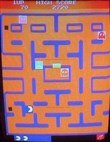
Bad 5C. (Thanks Mark Hook)
Plays, but monsters look like they've had a labotomy - heads cut off
RA3 output from 1E pin 11 goes in a chain sequentially to pin 9 at D1, C1, B1, A1 and then over to pin 13 at 2A, 2B, 2C and 2D. The problem shown in the photo was caused by an open between 2B and 2C such that 2C and 2D did not get the input. Ran a jumper to complete the chain to solve the problem. (Thanks Jeff F.)
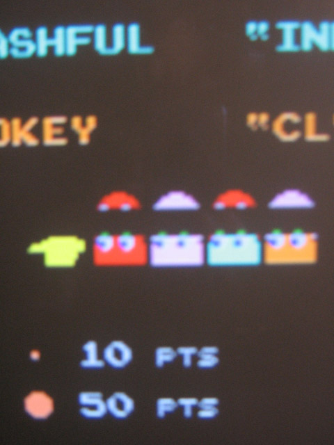
(Unknown issue - picture not available from archive)
Pins 2 & 3 shorted. (Thanks Dan Goett)
If anyone can contribute screen shots (or mock ups using MAME) I'd be happy to post them. I prefer 224x288 (Mame size), JPEGs but will take anything.
Inputs, Switches
Input Test using Test mode.
(Black toggle switch found inside coin door)
Up: sound made when eating a blue monster
Down: weird noise, when held down almost sounds like chopper blades
Left: "gulp" sound when eating fruit bonus
Right: warbling downward sound made when ms. pac is dying
Both player buttons should make the bonus ms. pac "ding ding" sound.
Coin switches make the coin drop sound.
(Thanks to Richard aka someotherguy)
All switches have 1 wire connected to the circuit board ground & 1 wire connected to the edge connector at the matching input. For more help troubleshooting faulty inputs or Dipswitches see logicprobe.html
Z80 Sync Bus Controller
It is easier to troubleshoot a known bad Z80 Sync Bus Controller
(Z80 SBC) in a known good board than to find it on a unknown board.
These piggyback boards are often installed backwards & powered up,
frying them. If you don't have piggyback board on an original board
or simply want new replacements see 284,
285 Custom Chips below.
Piggyback Socket
Both the SBC & the other piggyback board (V-Ram Addresser) have 2 small holes that nylon 'zip ties' are threaded thru & looped under the main PCB to hold the piggyback boards in place. This does not allways ensure that the board is sitting square & flush as the piggyback boards have some mobility despite the 'zip ties'. This will also conceal broken pins that can occur on the male socket of the piggyback board . It is not uncommon to see the 'zip tie' and the socket removed from the piggyback board which is then reinserted into the main PCB socket (female end) at 6S/5D. This is a "one time fix" as the PCB socket is expaned to accomodate the large square pins of the naked piggyback board. At this point the you will need to replace both the socket on the main PCB & the socket that is on the male end of the piggyback board. You will need to use a Double Wipe Tin Lead 28 pin socket, a machine pin socket will work for the main PCB but not on the piggyback boards.
U0 74LS139 if this fails the symptom will be the static garbage on screen. You can quickly diagnose this failure with a logic probe. Be sure that you have pulsing activity (full range high to low) on the input pins 3, 16 & 27 of the Z80 SBC (the 28 pins that connect the SBC to the main circuit board). Next check for ouput at pin 17. (You may want to look for pulsing at pins 10 & 12 of the 74LS139 also).
Pins 12 & 13 of the Z80 SBC are outputs of the timing section. Lack of activity at these pins could indicate problems after the 74LS139.(U1, U2 & U4)
U5 74LS244 is the buffer between the Z80 and the circuit board on the eight data lines. U5 only buffers data that flows from the Z80 to the board and is enabled by the output pin 9 of the 74LS74 at U2.
Symptoms of U5 failure vary. 74LS244's often will exhibit "noisey" or eradict outputs on a single line. Visually in Pac-Man this can vary from No Text on Intro Screen to Eradict Operation / Intermittent Crashes. The symptoms may be thermal related, becoming more frequent with time/ heat.
Diagnosing this is beyond the ability of a logic probe in most cases unless the outputs are stuck high or low. An Oscilloscope may help to spot "noise" or lines that fail to swing beyond the marginal range of TTL signals (0.8 to 2 V for 74LS244's).
V-Ram Addresser
The V-Ram Addresser is not plauged by being plugged in backwards as often as the Sync Bus due to it's size & the fact that it sits offset of the PCB if plugged in rotated 180' from normal.
Be sure to read the note about piggyback boards & sockets in the Sync Bus Controller section above.
Pin 11 of the 28 pin socket connector is sometimes used as a point to attach speed up kits. Inspect this pin for excess solder shorting to the adjacent trace or pin.
Plays, No Characters in Maze or intro Screen. Dots visible & disappear as eaten.
(rare case) Dead 74LS157 at U5 of V-Ram Addresser (rare case).
Plays, Screen Full of "F"'s on power-up. Intro screen full of red "1"'s.
74LS257 at U3 pin 3 out of circuit.
Plays, But Maze graphics from the bottom half are displayed on the top half also. Characters follow the original maze patterns.
Replaced 74LS257 @ U2 on VRam addresser board (Thanks Fred!)
Power Supply
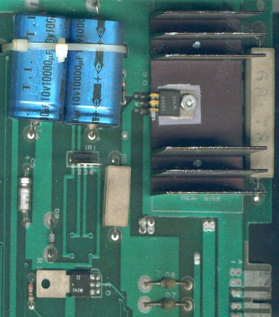
If you have a wavy picture, no blown fuses, and the filter caps of the power supply are connected securely, the problem is most likely a poor ground. Remove the yellow ground strap from the transformer mount and screw it to the metal case of the line filter. ("Frank the Crank" PlayMeter 8/15/85)
You need to troubleshoot the power supply section when
- your PCB does not have +5 VDC as measured across capcitors C2 or C3 (easy to get to).
- your games has no audio and you must first verify that there is +16 VDC for the audio amplifer.
- your game plays, but vertical "Hum Bar" (scrolling black/dark line on monitor about 1 inch wide).
Power the game OFF. Check all 4 fuses grouped together in the bottom of the cabinet (from the back door). To check the fuses remove them from the fuse holder (one at a time as not to mix up the different sizes) and Ohm them out using a multi meter. Visual inspection may not be good enough, using a multimeter to ensure that you have a good fuse is worth the extra minute.
Inspect the fuse holder as you check each fuse. The fuse holder must be clean and hold the fuse tightly, making a good connection. Replacing the fuse block is not a bad idea and may be necessary if you have a weak/ broken holder (see the Vertical Hum section).
Next inspect the edge connector & harness. You may have a RF filter board inserted between your main circuit board & harness. The RF filter board was meant to reduce radio frequency interferance caused by the Pac-Man game. Most operators have long discarded these filters since they cause more power supply connector problems and the RF interferance is not a problem.
You are looking for connections that are blackend or burnt. The fingers inside of the plug connector may have lost their spring and will not make a good connection to the PCB when inserted. Replace the edge connector if you find evidence of either situation.
To double check your inspection/ repair work so far, reconnect the board and harness & power on the game. Using the AC voltage setting of your Multi Meter measure the voltage from D7, unbanded side to D8 unbanded side. If all is well you should read about 14 Volts AC. A reading of near 7 Volts AC would indicate that one half of the AC voltage path is still faulty. Recheck fuses, fuse holders, and connectors to find the culprit.
Next measure the AC voltage from D3, unbanded side to D4 unbanded side. We are looking for about 25 Volts AC. A reading near 12 Volts AC would indicate that only half of the AC voltage path is working. Recheck fuses, fuse holders and connectors to find the problem.
NOTE the very last run of Ms Pac-Man cabinets did not use the normal AC tranformer setup as described above but used a latter MCR style transformer which is a much larger silver metal box with a Black transformer, large cylinder capacitors & Molex plug connectors. This particular setup does not supply AC to the Ms. Pac-Man board but DC voltages.
Next read DC voltage from ground to the top end of R52, about 12 Volts DC. Missing voltage here would indicate open R52.
Next read DC voltage from ground to BASE of transistor on Heat Sink, should be about 5 VDC.
Low Voltage 2~3 VDC when measured at C2 or C3. Resistor R53 4 Ohm 10 Watt gets warm. Measured Voltage from Ground to the Base pin of Q6 ( D44MV4 on the big heat sink, may also be a TIP 31 or ECG 377) Shows ~ 8 VDC.
Replace D44VM4. Be sure to install mica insulation & plastic sleeve on the the bolt too.
~ Note the pins on Q6 are marked on the board or refering to the above picture top to bottom
B) ase
C) ollector
E) mitter
Plays, But Vertical"Hum Bar"
Scrolling black/dark line on monitor about 1 inch wide.)
If you want to fix it one time & forget it, then change the 4 block fuse holder & Scotch-Brite the fuse ends. Next, get a Molex 22/44 edge connector with split pins (same as Jamma) and cut the wires about a ¼" up from the old never was a connector, one at a time & transfer them into the same positions in the Molex edge connector.
Solid Pac for a lifetime.....forget the caps on the pcb other than resoldering C6 & C7, as these sometimes have a cold soldered leg, about 2 percent of cases, but nevertheless a possibility.
When one of my ops has a Pac series trouble, you can bet it is on-board, because Molex keeps on ticking & the newer heavier fuse blocks last & last, unlike the flimsy ones originally installed. (Thanks to Bob Roberts For parts)
Check Zener diode D9. I've seen this diode go bad & shunt 5 volts to ground, even seen the game over fused and the diode heat up enough to be removed without a soldering iron.
IR1 is a voltage regulator.
Pac to JAMMA
Bob Roberts did a wonderful write up & pictorial on how to create a JAMMA (or whatever) adapter for Pac-Man. This also deals with the issue of supplying +5 VDC & +12 VDC in place of the AC voltages. Follow the Bob Roberts Pac-man JAMMA adaptor link to learn more.
Sound Problems
No Sound, Hum during Sound.
Rams @ 2L & 2K bad
Clicky Sound
Replace 74LS174 @ 1L
Buzz in music & after game over but not before start of game upon initial power up or reset.
Replace 4066 @ 1N. Placing O-scope on R1~R4 will show noise from bad 4066.
Distorted Intro Music - Other Sounds okay - Seems thermal/Cap like
Replace 74LS174 @ 1L bad on Pin 14. Bug trap only shows when starting game.
Muffled Sounds, seems like intro music is Slow.
Pin 10 @ 2L (RAM 7489/82S25) out of circuit.
Intermittent loss of Sound (Static)
Modification
- Cut trace to pin 1 of 2M (74LS273).
- Solder 1K resistor from +5VDC to pin 1 of IC 2M
-From Service Bulletin 5/19/82
Note
All chips in the sound section will bug trap.
Some Sounds seem ok, some seem bad /off.
Check R1, R2, R3, R4 for signals during Music / Noise. Each should
have 'Digital Waves' (squared, stair step sine waves as seen on an O-scope).
Lack there of go to 2M 74LS273 and check pins 2, 5, 6, 9, 12, 15, 16,
19 as these are all outputs.
Interesting "For Your Information" Content about Pac-man
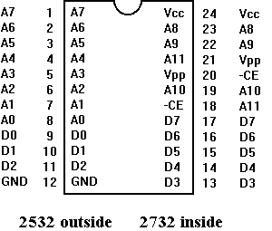
- 6E - Tie pin 18 to Ground, Tie pin 21 to A11 @ test point edge connector
- 5E - Tie pin 18 to Ground, Tie pin 21 to 4D pin 2
*Note this is for the pins lifted from the socket, to use the original socket would require you cut the original traces at pin 18 & 21 to isolate them first.
255 Split Screen
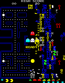
Split screen is true at screen 243 on Pac Man, Ms Pac just resets. This can be seen using the rack advance dip switch at 16 racks per minute for about 15 minutes.
Alternate Color for Ms Pac Man
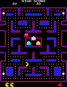
A strange feature/bug that may be noticed occassionaly when starting a Ms Pac Man is a blue maze. Seems to be related to booting up the game with a button pushed.
Pac MAD
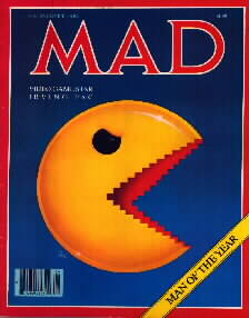
Many people have asked about Pac Man being on the cover of TIME magazine or being "man of the year" the only instance of this that I know of is the spoof by MAD Magazine. I have heard that Pac Man charactures were used on a cover of TIME but not related to video games. There was another issue of Time that did have an article about video games and a related cover but no actuall photos of games were used on the cover.
Made By Namco
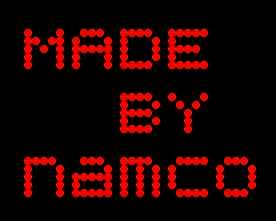
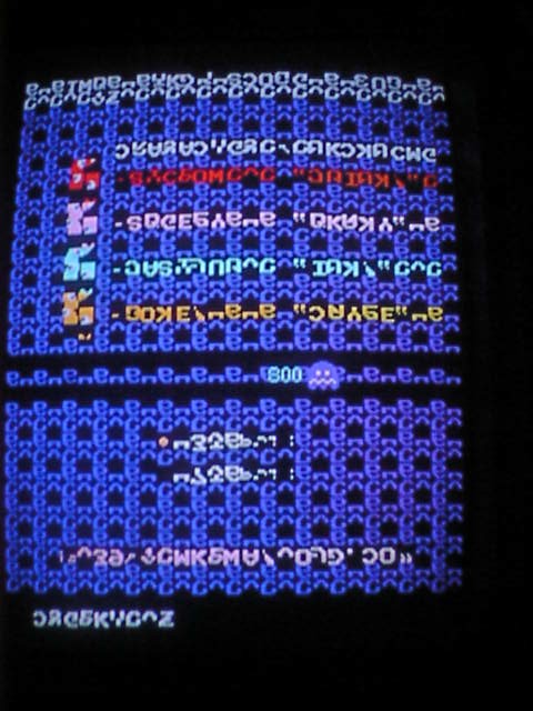
This screen had suprised myself & fellow Tech John Robertson in the past but we never had been able to repeat it or isolate it until a crafty programer/ hacker David Widel helped out.
This piece of code is found in the original Midway Pac-Man ROMs @ $3289. Place the game in the test grid screen (Monitor Convergence screen) by switching test mode on then quickly jiggling the test switch out & back into test. Next move the joystick
Up 4 times
Left 4 times
Right 4 times
Down 4 times
and you should see the above screen (rotated to match your Pac-Man monitor).
CAT Box Information
Game Roms can be checksumed using the Cat Box & Z80 interface
- 6E @ 0000
- 6F @ 1000
- 6H @ 2000
- 6J @ 3000
- 6M @ 8000 will crash catbox but read C9 21 00 40 CD 6A 94 etc byte by byte
- 6N @ 9000 boot Ms Pac setup.
KURZ-KASCH Tester
The Kurz-Kasch Test fixture, TF-650 can be configured to power up & play Pac-Man PCBs using the following cards...
- 345 A & B
- 171C or 287C
FLUKE 9010A w/ Z80 Tester
Pac-Man
0-F3F = $C64A
FC0-3E7F = $3101 (Speed Up)
FC0-3E7F = $81F1 (Regular)
3FC0-3FFF = $ A0FC
Ms Pac-Man (Boot)
0-F3F = $AC65
FC0-3FFF = $A084
8000-97FF = $2138
$5080 is Dip Switches 1-6 (7-8 are discrete circuits) $FF is all open.
($D9 is factory setting).
$5000 is IN0 inputs.
$5040 is IN1 inputs.
I've got test programs that I'd consider swapping with those willing to share like programs.
Signature Analysis
Sync Circuit
Start going low
Stop going high
Clock going high
3R 74LS161 (1st Sync)
Clock on 8C pin 3
Start/Stop on pin 11 = $UP73
15 = $0000
14 = $334U
13 = $0U16
12 = $00UP
11 = $0000
10 & 7 = $55H1
3S 74LS161 (2nd Sync)
Start/Stop on pin 11 = $6PCP
15 = $0000
14 = $3CPF
13 = $A70F
12 = $6PCP
11 = $0000
10 & 7 = $4F35
Check 5M pin 9 = $8908 this means 3N good & 1/2 of 5M good.
2R 74LS161 (3rd Sync)
Clock on 3N pin 8 (6Mhz)
Start/Stop on pin 11 = $UP73
15 = $0000
14 = $334U
13 = $0U16
12 = $00UP
11 = $0000
10 & 7 = $55H1
2S 74LS161 (4th Sync)
Start/Stop pin 11 = $00UP
15 = $0000
14 =$00UP
13 = $00UP
12 = $00UP
11 = $0000
10 & 7 = $0001
ROW 6 ROMs
Watchdog out.
Z80 NOP
Start going low
Stop going high
Clock going high
1 = $A3C1
2 = $7211
3 = $AA08
4 = $C4C3
5 = $0772
6 = $7050
7 = $C113
8 = $H335
9 = $9C92
10 = Data
11 = Data
12 = $0000
13 = Data
14 = Data
15 = Data
16 = Data
17 = Data
18 = $89F1
19 = $HH86
20 = $FU4U
21 = $755U
22 = $577A
23 = $7707
24 = $755U
Pin 20 varies according to location
6E = $FU4U
6F = $A207
6H = $H6A3
6J = $HU34
Pin 18 of 6K, 6M, 6N, 6P = $UF9P
Pin 27 of 6D = $64HU
Pin 6 of 7L = $AC99
MS Pac Bootleg Hack Signatures.
A15 = $0000 pin 27
A13 = $PCF3 pin 26
A12 = $AC99 pin 2
A11 = $89F1 pin 23
AUDIO
3L
1 = $7550
2 = $0772
3 = $U7H8
4 = $U7H8
5 = $7050
6 = $1779
7 = $1779
8 = $0000
9 = $A66A
10 = $A66A
11 = $C113
12 = $0000
13 = $0000
14 = $H335
15 = $0000
16 = $755U
2L
15 = $A66A
14 = $1779
13 = $U7H8
1 = $0000
3M PROM PM1-2
Clock on 8C pin 3
Start/Stop on pin 3
2 = $0808
3 = $0000
4 = $00UP
5 = $55H1
6 = $334U
7 = $0U16
Also Check
3L 74LS157
3 = $0808
6 = $0000
10 = $00UP
13 = $0U16
3K 74LS158
1 = $334U
Pac-Man O-Scope Pics
(not online at the moment)
ROMS & EPROMS
Almost all original Pac man boards used masked Roms (9332Bs) that are black, some of the latter Ms Pac Mans had eproms (2532s) with white paper stickers over the windows. The pinouts of the 9332B and 2532 are compatible.
To identify rom chips read the top line of print...."0072-M932D-"
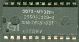
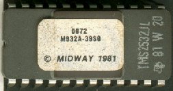
- M932A-39S0 = 6E
- M932B-39S0 = 6F
- M932C-39S0 = 6H
- M932D-39S0 = 6J
- M932E- = 5E
- M932F- = 5F
Note that the letter after 932 is the position indicator.
I am not sure of how to read the second line but you will notice the 9332B, which is a reference to the format of this chip. The 9332 is the equivalent of a 2532.
The second chip (right side) is a EPROM.
Third line is the MIDWAY Copyright (1981) for most Pac Man games (though it was introduced in 1980).
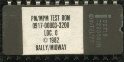
I purchased this ROM from the net. This is for the Midway Test Fixture.
Software Revisions
Midway has available now a new program for their hit video game "Pac-Man". The new program increases the difficulty of the game and adds a new challenge to players already familiar with the original.
The new program kit consists of 2 Roms (PM2/24) that replace existing Roms in locations 6E and 6H on the main logic board.
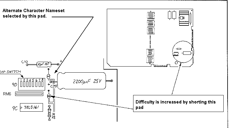
When installing the new memory devices, it is recommended that the difficuly jumper (See top of page) be removed. This jumper may then be replaced after the players are proficient with the new program for an extra added degree of difficulty.
-As appeared in December 81 Star Tech Journal
The checksums for these 2 chips are identical to the originals but comparision show otherwise in about 14 bytes.
Color PROMS
 There are 2 color
proms that dictate the final color of the maze and character. Pac
Man & Ms Pac use the same color proms, other games may vary (see "How
many games run on the Pac Man board?).
- 4A PM 1-4 - 256 x 4 PROM (82S126N, 1M 5623, 63S141) Tri State 82S129N will work.
- 7F PM1-1 - 32 x 8 PROM (82S123N, 7603)
Note that these color Proms are only half full of data which is normal and allows for a switchable design if you wanted to make new color proms & toggle the highest address line manually (Clay used this approach on his hack).
To patch color PROM 7F load & burn data at $10 then cut split pad open above 7F.
To patch color PROM 4A load & burn data at $80 then cut split pad
to right of 4A (don't solder shut).
RAMs, Video RAMs
4K (low bits), 4N (high bits) are Character Data $4000 - $43FF
4L (low), 4P (high) are Color Data $4400 - $47FF
4M (low), 4R (high) are Scratch Data $4C00 - $4FFF
Bob Roberts or
Jameco (www.Jameco.com)
93415 @ 2A ~ 2D
Replacements may be
2115 or
2125 (intel)
B.G. Micro (www.bgmicro.com)
Part # ICS212570 (2125A-2 1Kx1 70NS) Thanks Andy
7489 or 82S25 @ 2K, 2L & 3F, 3H
2K, 2L are part of the sound section.
3F, 3H are part of the video output section.
Jameco (www.jameco.com)
2148/6148
Seen on Pac3 style bootlegs as single chip replacement to the four 93415 RAMs.
Pac-man / MS. Pac-man Conversion Hack (EPROM Only)
A Pac Man board can be modified to a Ms. Pac board by removing the ROMs in the 6th row & performing a hack. Check out that Pac-man hack at PinRepair.com.
You must also change the 2 character ROMs at 5E & 5F to Ms Pac character ROMs.
If someone wanted to get real fancy they could look into making the color Proms switch able too! If you notice on the schematics both 7F & 4A have the highest address line pulled low (but also attached to a split solder pad) Seems to me you could move altered color code to the other half of the chip & pull these high address pins to a toggle.
Thanks go to Doug Jefferys Chris Cope and Richard Schieve for help & motivation with the hack!
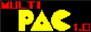
Clay Cowgill had developed a Pac Man multi game auxiliary board that has a on screen menu to choose your game (1 of 24 variations of Pac Man or similar games). Unfortunately the items is no longer available due to concerns with Namco lawsuits.
PAC-Man Super ABC Kit aka 16 in 1
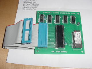
Two-Bit Score also develeoped a Pac-Man multi game auxiliary board known as Super Pac-Man ABC. This kit contained less variations, 16 Total and was designed to be street or operator friendly requiring no external reset button. Two-Bit Score ceased sales of these units in the Fall of 99 due to threats of Namco lawsuits.
High Score Save (and multiple games)
Soon to be available kits include....
4 Ms Pac Variants plus High Score save.
128 variations of Pac-Man plus High Score save.
All kits include a configuration menu and 10 high score saves (by 11 letters).
See Dave Widel's Arcade Game Kits page to check out his other game hacks!
How many games run on the original Pac-man board?
(I didn't count all the new graphic variants, only 1980's era original games and modifications). This list of games that run on the original Pac-man board are as follows:
- Pac-Man
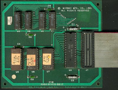
- Ms. Pac-Man (requires auxiliary board shown below & 2 new eproms at 5E,5F).
- Pac Man Plus (requires auxiliary board (epoxy coated shown below), 6 new eproms & 2 new color proms 4A, 7F).
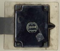
- Jump shot (requires auxiliary board (epoxy coated similar to Pac-Man Plus), 6 new eproms & 2 new color proms 4A, 7F).
-
 Shoot the Bull (requires
auxiliary board (epoxy coated See Pac-Man Plus), 6 new eproms & 2 new
color proms 4A, 7F)
 -
 . Piranha eproms
& alternate color PROMS.
 - Driving Force requires additional kludge board & severe hacking.
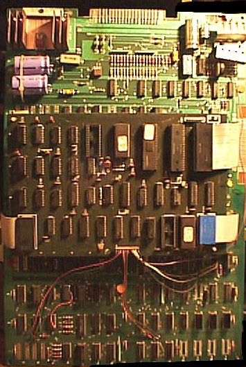
- Eyes eproms only. (see bootleg section too)
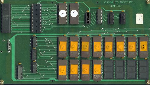
- Big Bucks Trivia game. Requires a custom auxilary board pictured below.
- Make Trax (Same as Crush Roller but with the Williams copyright and protection circuit)
-
 Lizard Wizard by
Sunn International 1985. Originally required epoxy coated auxiliary
board, 6 new eproms & 2 new color proms 4A, 7F but now available in
EPROM only format (still need alternate color proms). Big thanks to the
efforts of Mike Balfour.
 -
 The Glob
  Super Glob (auxiliary board- 2 2732 EPROMs 1 PAL & several TTL
chips)
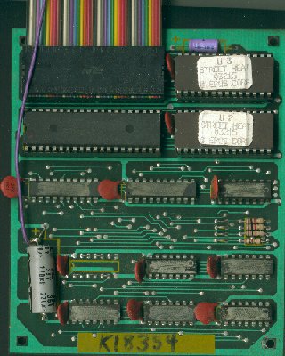
(Ignore the "Street Heat" labels on the EPROMs, this board is identical in appearance to THE GLOB, Super Glob, Beastie Feasties & Boardwalk Casion. It has EPOS on the board.)
- Eeek!?
- Mr TNT! Eprom Swap. Requires single button for speed control (not hardware speed-up button).
- MTV Trivia Similar in design to Big Bucks.
- Pinky's Maze ?? "The new game intros new characters and a choice of 16 different mazes" I have an ad for this conversion kit but do not know anything about it nor have I ever heard anything about it....
- Penta/Pengo a decrypted version of Pengo will run on Pac Man with a slight modification.
-
 -Beastie Feasties runs on a The Glob PCB
 - Ali Babba & the Fourty Thieves- Runs on a modified Pac-Man (more RAM/ ROM)?
- Super Zola Pac Girl-unusual hack 27512 with game timers in some modes
- Boardwalk Casino looks the same as The Glob PCB. Play Black-Jack, Joker Poker & Hi-Lo. Trying to decrypt this for MAME.
Alternate Mazes?
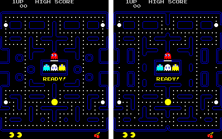
Hagley Man - Puck Man
Get Hangly Eprom zip file (hangly.zip)
Get Puckman Eprom zip file (puckman.zip)
Ms Pac Attack This appears to be the same mazes as Ms Pac Plus but in different order (Zig Zag is too hard for first screen...) Bonus levels are same as original Ms Pac. Single 2532 Eprom that plugs in U6 on the auxiliary board. Available from Two Bit Score.
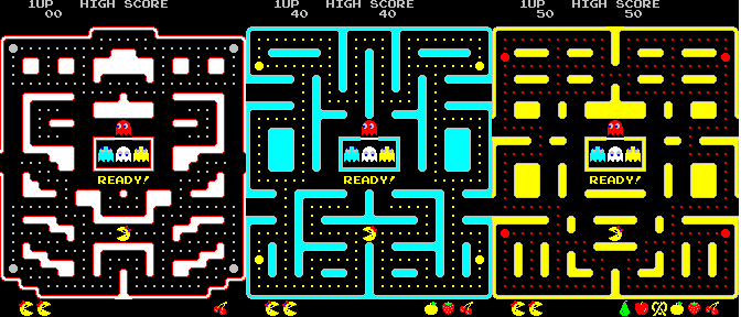
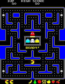
Ms Pac Plus/Miss Pac Plus I believe this was created on the East coast possibly VA (Marty Stein, Pinball Wizard?). 4 alternate mazes named.. #1 Zig Zag (cascading steps in the corners), #2 The Trap, #3 Red Eye Run, #4 The Hook. Bonus levels are 35000, 65000 or 95000. I've seen this available on a bootleg auxiliary card with 3 2764 eproms & a *PAL* of some sort (could be a 82Sxxx series chip?).
I have decoded this and made it available to run on the bootleg setup, currently it is mistakenly refered to as Ms Pac Attack.
Get Miss Pac Plus Eprom zip file (Mspacatk.zip)
Ms Pac 6M unusual maze variant that has not 4 different mazes but 6. This particular board was found in Canada (thanks to Gene & Sils on help with this).
Alternate Characters?
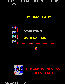
Heartburn
Firefighting theme, designed to drop in to a Ms Pac Man setup (5E, 5F), available from Two Bit Score
Desert War Ms Pac man character conversion where our hero, Pac flies an airplane against 4 SCUD missles that become DUD missles when deactivated by eating a power pellet. Programmed by Mike Naylor and distributed through out Florida.
Get Desert Storm Eprom zip file
Popeye Pac man is replaced with Popeye (the
sailor man) head, complete with pipe. I have been told that the dots were
hearts but I have not seen that.
Well yes there is a set of roms that has hearts in place of the dots, thanks to Rick in Canada for the data. Get Hearts dots Eprom zip file.
Arcade Graphics Editor by Ivan Mackintosh allows you to edit the character set for Pac-Man and alot of other games.
Pac-Man Patches & Name Editor program by Marcel Silvius, alternate graphics and a name editor.
Crush Roller will run on the Pac-Man PCB if you merge the files in the following format. This game is nearly identical to Make Trax by Williams with the only variations being in the name, copyrights and a small security chip.
The CR images should be combined as follows:
- CR1 \ pacman.6e
- CR5 /
- CR2 \ pacman.6f
- CR6 /
- CR3 \ pacman.6h
- CR7 /
- CR4 \ pacman.6j
- CR8 /
- CRA \ pacman.5e
- CRC /
- CRB \ pacman.5f
- CRD /
Thanks to Han!
Speed Ups (Overview)
Speed ups will make the speed of Pac-Man faster than the ghost or will make the speed of all on screen characters proportionately faster.. These 2 different categories reflect the method used to create the enhancment. Software (ROM) speedups make Pac-Man much faster than the ghost. Hardware ( board modifications, extra wires etc) make all on screen characters move equally fast.
Speed Ups (Software)
Pac/Ms Pac
In the EPROM at 6F change byte $80B from BE to 01. The last byte ($FFD) of the 6F rom is usually changed from 00 to BD to give the rom the same checksum.
Possible to speed up other games based closely on the code (Jr Pac/ Pac Man Plus)
CHEAT EPROM This software modification was created by, Dock . It replaces ROM 6F like a normal speedup but it allows you to ...
- a) speed up game by pressing Player Start 2
- b) become invincible to monsters by pressing Player Start 1.
There is a new variation of the software speed up with additional patching to remove the speed up from demo & intermission screens (where the Pac-Man over runs the characters).
Speed Ups (Hardware)
Speed Demon
Speed Demon is a interesting method of obtaining a player selectable game speed (regular or fast). After you insert coins you hold the joystick up while selecting 1 or 2 player mode, this will place the game in fast mode and it will remain that way until another coin is inserted. This was sold as a enhancement kit to operators as it included a small PCB (3 chips, one is a 4011 & a 1N4004 diode) and instructions on how to preform the regular hardware speedup which is selected by the Speed Demon PCB. The hack does have problems handling multiple credits (don't know what it does in free play) .
Variable Speed Speed up
<place picture here>
Pin 1 - GND
Pin 2 - Cap - 6
Pin 3 - Output
Pin 4 - +5VDC
Pin 5 - no connect
Pin 6 - Pin 2 / Resistor
Pin 7 - Resistor / Variable
Pin 8 - +5VDC
New Jumper back of 8C
Bourns 335S, 500K pot.
Bizarre Speedup Hack 1
Short pins 2 & 3 together on chip 5M. Credit & Fruits will display along the right side of the maze as well as on the bottom but it runs faster!
Hack 2
- Clip Pin 11 on 8C (74LS74).
- Run a wire jumper from the chip side of the clipped pin 11 to pin 12 at 5S.
This will double the speed of your game, if you were to use pin 11 at 5S you would have 4X, pin 10 at 5S would be 8X etc.
Hack 3
I will soon cover this hack that has a push button for speed up control.
Little Black Box

This is a small rectangular black box about 2 inches long and a 1.5 wide with wires coming out of the top and connected to the pac man board in a few spots. I'm not sure who made this and I have seen home made versions of the same thing. I know one local (Central VA) technician that used the small plastic cup "ketcup containers" to build his own version of the little black box speedup.
Wire hookup for Little Black Box
- White - 5M pin 5
- Black - PCB ground
- Red - PCB +5 VDC
- Orange - 8C pin 11, lifted from the board (or cut trace)
- Green - 5S pin 12 (note 11, 10 etc could be used if a higher speed was desired)
- Brown - Push button switch on control panel or SPST switch to change speed when grounded.
I may have a couple of these units available for sale yet, email me if interested.
Pause Switch
Wouldn't it be great to have a pause switch so you could take time out to answer the phone, get a snack or what have you? Well Pac Man PCBs actually have a pause switch built in, Dip Switch number 8 will pause your game, the only problems with this approach is
- Hard to reach the dip switch from the playing position.
- The sound remains stuck in a loop.
- Screen is subject to burn in.
Well the first two are easy, remote the dip switch 8 by wiring a switch in parallel and use a switch to open circuit the Speaker circuit. This could be done on a DPDT switch mounted inside the coin door. The third point is one I don't have a simple solution for other than don't leave the game paused for too long (days on end....).
Coin Door Lock
Bally/Midway coin doors & most all over/under coin doors use the 7/8" cam lock set with a 1 1/8" straight cam. You can use the 1 1/8" cam locks in place of them by going to the ¼"offset-in cam. All this does is make up the ¼" difference in barrel length between the 7/8" barrel & the 1 1/8" barrel. Some of the older games used the 5/8" cam locks with a straight cam & again, you can go up a size to the 7/8" lock set & use the ¼"offset-in cam to make up the difference.
Back doors are most commonly 1 1/8" locks with 1 3/4" straight cams. There are exceptions that need the ¼"offset-out cam to get past a center door stop, or use a 1 3/8" lock set with a straight cam. There are also a few that use the 7/8" lock set with either the straight or ¼"offset out cams as they are recessed into the back doors' wood to allow for barrel length differences.
Some brands of lock sets use cams that are reversible & used as either offset-in or out as they have no stop tab. 90º movement is accomplished by a notched spacer which can be any degree from 90º to 270º which is placed on the end of the barrel & the stop tab is actually on the barrel housing rather then on the cam itself. Cams with the stop tab can be used in reverse situations, but they will spin 360º with the key in place...no stops.
Once installed, you can have slop on most of them and the best way to remove it & get a tight door fit is to remove the control panel and lock the coin door. Pushing in on the coin door you can now eyeball or measure the distance between the cam & the door strike. It is tempting to just grab a pair of pliers & bend it in to meet the strike, but this will do several things. First it will mar up the cam at the very least & there is a danger of breaking the retaining screw in the end of the barrel, and secondly, if your barrel is a strong one, it will bend your coin door front out of flush.
The best way to do this is to remove the cam taking note of the direction you need to bend it in. If you have the luxury of a bench vice, you can put a couple pieces of paneling in it to act as a cushion so you can place the cam in between loosely and using a pair of pliers on the barrel end of the cam, gently bend it to the position you need & then retry it on the door.
If you have no vice or are on location for ops, you can grip the cam in the same manner with the pliers on the end that goes over the barrel, and place the end of the cam on a concrete floor or sidewalk & step down on the pliers with your foot to accomplish the same bend without screwing everthing up.
The jaws of the pliers in both cases aide in protecting the barrel end of the cam from bending out of shape & not seating back onto the barrel properly.
Once your top door is tight in the over/under case, you will want to make a duplicate cam for the bottom door & once you have both secured you can replace your control panel.
The same applies to the back door with the exception of measuring the distance you want to tighten. First install the closest fitting lock set to needed & then turn the key to an almost locked position and pull on it to see the distance the back door will pull away from the cabinet to judge how much of an offset bend you'll need in the cam to make for a tight fitting door.
Thanks to Bob Roberts for the in depth type up!
Back Door Key
Original back door keys are Illinois #350 or #1355 and may also be found on Rally X & Gorf.
Credit Multiplier Board
Credit by pass board wires pins 1 & 2 to pin 4, pin
5 is a key.
The Credit Multiplier Board does just that, it takes a single coin switch input & multiplies it by a factor set by dip switches. The credit multiplier board is mounted inside the back cabinet opposite the main PCB. I've never seen an actual credit multiplier PCB and assume that it was for non USA games?
In place of a credit multiplier is a Credit Multiplier Bypass board, a small PCB with a single row of Molex header pins that plugs into the harness. The schematics of a credit multiplier are show in a Pac-Man manual. Notice also that any cabinet wired for a credit multiplier board installation will have 2 coin meters, not one.
Light Bulbs
Mini Marquee
194 Bulbs 14V wedge (5 needed)
Cocktail Table
194 Bulbs 14V wedge (4 needed)
Cocktail tables have a different transformer with a seperate fuse for the coin door lights, 1 1/2 amp slow blow.
Coin Doors
1895 Bulbs 12V Bayonet (1 or 2 needed)
Florescent Marquee
18" Cool White (18TCW)
Starter ?
A cheapie "under the counter" style florescent fixture from you local hardware may be an easier fix than replacing ballast.
Fuses
Fuse size depends on cabinet & actual wiring. Latter issues of Ms Pac cabinets increased the 1 side of the 12VAC fuse from 1 Amp to a 1 1/2 Amp Slo Blo fuse to also accomodate the coin door lights. Refer to the label next to your fuses in the bottom of the cabinet first.
All Cabinets
1) 2 Amp Slo-Blow Fuse for the main AC input. Short in electric
wall plug may blow this fuse.
1) 2 Amp Slo Blo Fuse for monitor feed (this is not the fuses on the
monitor itself)
Cocktail only
2) 5 Amp Fuses for 7VAC
2) 1 Amp Fuses for 12 VAC
1) 1 1/2 Amp Slow blow for lights
Upright & Mini
2) 5 Amp Fuses for 7VAC
1) 1 Amp Fuses for 12 VAC
1) 2 Amp Slow blow for lights & 12 VAC or older cabinets may
just be 1 Amp!
Fuses & fuse holders must be free of corrosion and the fuse holders must tightly grip the fuses. Bob Roberts sells replacement fuse holders if yours is weak, corroded or broken.
Pac-man Cabinet Dimensions
Upright
Height 73 inches
Width 26.5 inches
Depth 24 inches
Weight ?
Mini (Caberet)
Height 60.25 inches
Width 19.5 inches
Depth 24 inches
Weight ?
Cocktail
Height 29 inches
Width 32 inches
Depth 22 inches
Weight ?
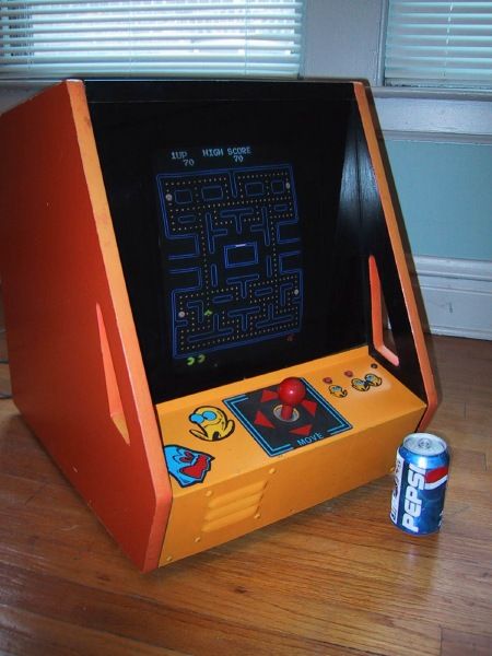
Counter Top
Yep there was actually 1 prototype that showed up on E-bay in 2001. It was an attempt to pitch selling home machines through high end catalog stores that never came together.
Paint / Cabinet Restorations
Links
http://netdirect.net/~astewart/arcade/
Ms Pac-Man Blue
Dutch Boy color "Pacifica" (2-B-4) is a perfect match. (Thanks Jeff Destross)
- Glidden - Passion Flower - 30RR 26/335 (Blue)
- Glidden - Rhapsody - 50BG 61/306 (Pink)
- Glidden - Sunny Side Up - 37Y 61/877 (Yellow)
I used a flat color and am going to protect it with a gloss, but you have the option for flat or gloss....I think if I did it again, I would try. (Richard from the Newsgroup)
Replacement T-Moulding
Orange Replacement T-Moulding to match the original Pac-Man
color is available from T-molding.com
25 feet will leave you a bit to spare on a dedicated pac-Man.
Tools: Rubber Mallet (or some no mar hammer device), Screwdriver, Knife or shears.
To remove the old T moulding simply take a screwdriver & pry free the old moulding from one end top back or bottom front).
Pull the old moulding out by pulling directly back in the same plane as the cabinet side (in other words don't try to pull the old moulding at an angle so that you could crack or break your cabinet, with plywood Pac-Man cabinets this shouldn't be an issue but with particle board it may be).
Once you remove both pieces you may notice that some spots the insert part of the original moulding was cut out. This is done to allow the T moulding to bend to a tight radius curve. You will need to duplicate these cuts as you install the new moulding.
Begin by inspecting your groove and ensure it is clean & clear of debris. Place the new T-moulding in the grove starting at the bottom. At the first corner rising up the front of the machine by the cash box you will need to notch the rib. A "V" shaped notch or even a bit wider is okay. You want to remove enough of the rib to make the curve fit tight into the groove but no more than needed.
Continue to work your way up the face of the cash box area, seating the moulding with your mallet as you go.
The tight curve at the Control panel will require another notch similar tothe first. The top front & top back will also require notches.
Some operators prefer to nail the ends of the T-moulding in place. This should not be necessary as long as the groove was clean & the rib fit snuggly.
Control Panels
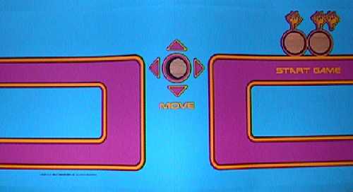
This is a factory Ms Pac Overlay for a Super Pac-Man control panel. Notice the side by side player select button arrangement & the alternate striping. Midway also provided an adapter harness to convert from a Super Pac-Man wiring harness to a Ms Pac-Man board. (place that picture here too!)

Replacement Overlay sold by WICO.
How to remove the Joystick?
- Remove "E" clip from bottom shaft of joystick. (I use a small thin blade screwdriver)
- Remove red plastic switch depressor.
- Tug for all your worth & discover that the red knob will not pull thru the control panel.
Very common problem. The metal shaft of the joystick is probably coroded/rusted to the metal bushing in the "centering grommet".
You can try WD-40 or other penatrating oils but it probably will take more. One unusual trick is to use a "cola" soda and soak/immerse the bushing/shaft section for a period of time. (The acid content of the soda helps loosen the rust).
If the soda trick fails you pretty much have no option other than cutting the bushing (if you are trying to save the joystick).
Ribbon Cables for Ms Pac Man & other Auxilary Boards
These are pretty easy to make...
Order at least two of part #42712 (.100" IDC Flat Cable Plug, 40 pin - Originally part #42711, but discontinued) from Jameco (800-831-4242). Crimp them onto a 40 pin ribbon cable (a piece of IDE hard drive cable will work fine) and you're ready to go. You can use a pair of pliers to do the crimping, although the "73251" (IDC Crimping Tool) will a better job for $15. Order more than two of the connectors (even if you only need two) 'cause you might mess up the first one you try...
If you'll even need to make more than a couple ribbon cables the investment in the tool will save you time and $$$ in the long run.
-Clay (Cowgill)
FAOQ (Frequently Asked Other Questions, ones that haven't been covered yet)
Can I run Super Pac Man on a Pac Man PCB?
No, Super Pac Man is a 6809 based game & will not run on a Z80 based system.
Can I run Jr Pac Man on a Pac Man PCB?
No, not yet but it may be possible. I have parts of a board that supposedly did this. I have not proven it to work, but I cann't prove it impossible either!
Can I run Baby Pac Man on a Pac Man PCB?
Well what about the pinball parts? Completely different system here.
How can I tell if my board is bootleg or original?
All Midway boards will have the "Midway MFG. CO" and other identifying marks in the etched into the printed circuit board in the middle section, you cann't miss it. Bootleg boards are often times smaller & run on DC voltages thus have no large heat sink & huge capacitors like the original board.
On my Ms Pac Man, when I power up the game the coin meter (counter) clicks 2 times, Why?
You have a bootleg conversion and not the original auxiliary board conversion. Does Clay's kit do this?
Can I take a transformer (panel/wiring harness) from an upright & place it in a cocktail table?
Yes, But the transformer in the cocktail table has an additional set of 12 VAC taps on the Isolation transformer for the "extra" lights over the control panels.
284, 285 Custom Chips
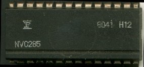
Originally the two sockets 5S and 6D were to house 28 pin custom chips but high demand & production problems forced Midway to manufacture the two piggyback boards using discrete TTL chips. Unfortunately these piggyback boards are often destroyed or simply missing in action. The custom chip pictured above is from 6D. 5S would have a NVC284 chip, which appears to be even rare than the NVC285. The custom chip (6D) is handy for troubleshooting as it allows easy access to the CPU pins.It is also possible to find this chip (NVC285) on Rally X boards.
Clay Cowgill has done it once again and designed a simple solution for these two buggers. Visit Clay's Pacman Daughtercard Replacements Page for more information
Clay Cowgill & JROK have combined to create a newer replacement 284/285. This version is the same size as the 28 pin sockets they plug into (similar to the rare custome chips). I also understand that these are supposed to withstand reverse insertion?
Mark Spaeth offered replacement 284/285 boards that are an updated version of the familiar Midway plug in boards. They are a tiny bit smaller than the original ones but are made up of the same TTL chips & repairable if need be.
Bootlegs
Being that Pac-Man and it's spawn were such a popular item they garnered some of the highest flattery of the industry and some seedy elements too. The seedy elements being illegal production of boards that looked like & played just like Pac-Man but were not made by Midway.
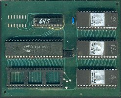
The above board is a unathorized Ms Pac-Man auxiliary board. It is similar to the original auxilary board in that it plugs into the Z80 socket at 6B viva a ribbion cable. It is different in that it uses a single PAL chip & 3 2764 EPROMs to replace the ROM code found on the main PCB. (NOTE, you must still replace 5E, 5F character/maze chips to finish the conversion BUT unlike the original Ms Pac-Man you do not need original roms or any roms row 6!).
I've seen 2 variations of software used on this particular board. The EPROMs are marked "A", "B", "C" or "E", "F", "H" with the first set being a normal Ms Pac-Man and the second set of 3 being Miss Pac Plus (see Alternate Mazes? for more on this). The EPROM data is in a scrambled format (not straight forward addressing) in a attempt to thwart easy copying. The placement of the Z80 varies according to the PAL chip used.
If PAL = 65S then Z80 is by B/F ROM.
If PAL = 64K then Z80 by A/E ROM.
A = $DB4A
B = $0554
C = $ADB3
E = $70BD
F = $F85C
H = $144F
2764 ROMS
This board is similar to the above series but has 3 TTL (?) chips
and is marked 2764 ROMs in the foil pattern. These ROMs do not seem
to be scrambled format.
A = $ B315
B = $ADAC
C = $AB2D
I find the above boards very handy for my troubleshooting, coupled with a known good ribbon cable I can insert this aux board into a broken Pac-Man board & know if I have a problem in the main ROM area (row 6 roms) or possibly a bad Z80.
Sex Change
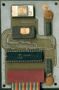
The above board is marked "Sex Change" on the back. It has one 2532 EPROM and one 2716 EPROM plus a 7400 and 74LS138 in addition to the Z80. This particular auxiliary board is designed to convert a Pac-Man pcb into a Ms Pac-Man but it requires new (bootleg) EPROMs for all of row 6 & row 5 ROMs on the Pac-:Man board.
Alternate Ms Pac-Man Auxilary Board w/ extra chips
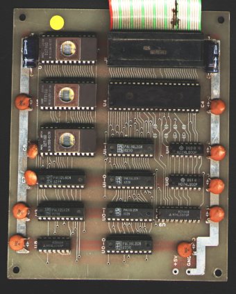
2nd Alternate Ms Pac-Man Aux board?
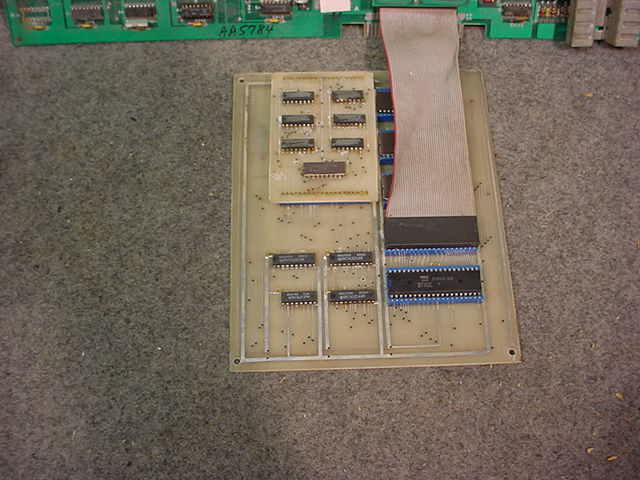
Thanks to Steven T for pointing this one out!
Super ABC board - by Two Bit Score
Bootleg Pac 3
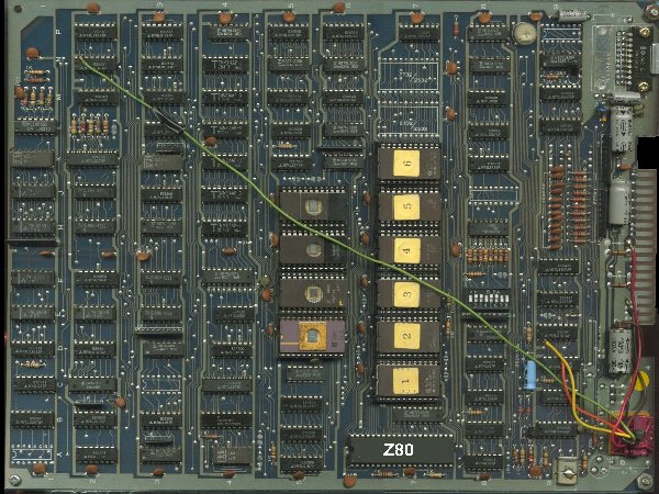
Notable Items of this board.
- Pin 1 is nearest the crystal.
- 2 positions marked for audio pot. (One near each amplifier)
- Designed to use either HA1368 or HA1366WR audio amplifier at the top or MB3712 at the bottom.
- Designed to use either 2732 or 2532 EPROMs depending on Jumper pads (above is using 2716s for row 5 & 2732 for row 6).
- Above board has additional push button speed up kit installed (colored wires & red board in bottom corner).
- Componets for some switch inputs are missing, namely capacitors & resistors for Test Switch & Table switch.
There are a few variations of this board family...
PAC3 is a Pac-Man board with only 8 EPROM sockets & MB3712 Audio Amplifier chip. MP2621 board requires a jumper wire from 8E pin 13 to Z80 pin 5.
MPO1 is 2nd Generation Pac 3 with 8 sockets (or landings for sockets) in row 6 and 4 sockets in row 5. This board is pre configured to run Ms Pac-Man bootleg software with wiring for the A15 to ROM Select circuitry.
To modify PAC3 4 socket row 5 to 2 2732s (from 2532s).
Cut pin 21 from 24 of 5F on back of board & Jump Pin 21 to 4E Pin 1.
Cut pin 18 5E from trace on back of board & Jump Pin 18 to GND.
| Solder Side | Parts Side | ||
| GND | 1 | 2 | GND |
| GND | 3 | 4 | GND |
| GND | 5 | 6 | GND |
| Speaker + | 7 | 8 | Gnd (Speaker -) |
| +12 VDC | 9 | 10 | +12 VDC |
| 1 Player Up | 11 | 12 | nc |
| 2 Player Up | 13 | 14 | |
| 15 | 16 | ||
| +5 VDC | 17 | 18 | +5 VDC |
| 19 | 20 | 1 Player Down | |
| 21 | 22 | 2 Player Down | |
| 2 Player Start | 23 | 24 | Coin Counter |
| 1 Player Start | 25 | 26 | Coin |
| 1Player Right | 27 | 28 | |
| 1Player Left | 29 | 30 | Video Red |
| Video Blue | 31 | 32 | 2 Player Right (?) |
| Video Green | 33 | 34 | 2 Player Left |
| Video Sync | 35 | 36 | Table ** |
** The associated componets (Capacitor/ Resistor) may not be on board, thus this pin may not work. Often bootleg boards are hard wired for Cocktail Table mode.
Pac 1 / Pac 2 Bootleg
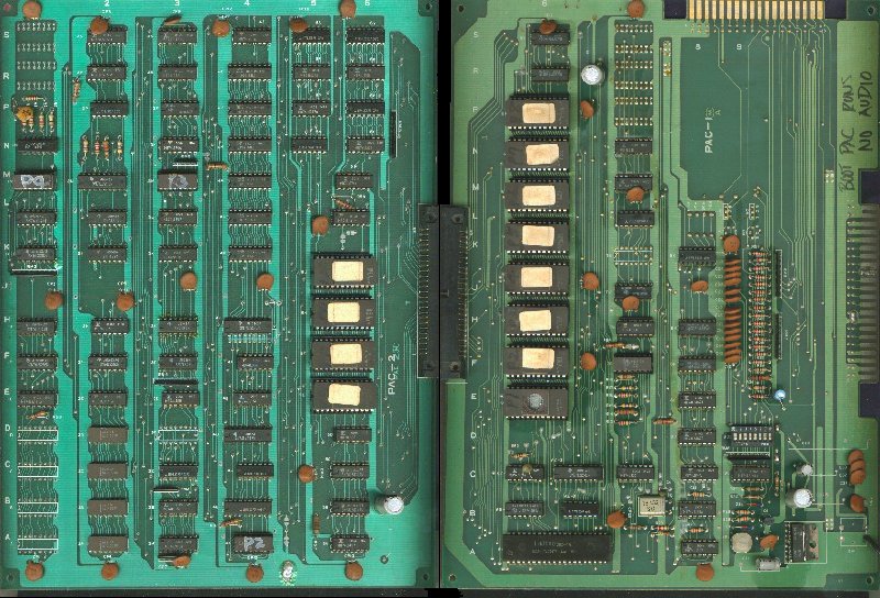
| Parts Side | Solder Side | ||
| GND | A | 1 | GND |
| GND | B | 2 | GND |
| +5 VDC | C | 3 | +5 VDC |
| +5 VDC | D | 4 | +5 VDC |
| +7.5 VDC Unregulated | E | 5 | +7.5 VDC Unregulated |
| 1 Player Start Lamp | F | 6 | 2 Player Start Lamp |
| Lock Out Solenoid | H | 7 | Coin Counter |
| Coin 1 Switch | I | 8 | Coins 2 Switch |
| Test Switch | K | 9 | Service Switch |
| 1 Player Start | L | 10 | 2 Player Start |
| 1 Player Left | M | 11 | 1 Player Right |
| 1 Player Up | N | 12 | 2 Player Up |
| 2 Player Left | P | 13 | 2 Player Right |
| GND for Table Mode | R | 14 | 1 Player Down |
| GND | S | 15 | GND (use for Speaker -) |
| Video RED | T | 16 | Video GREEN |
| Video BLUE | U | 17 | Video SYNC |
| 2 Player Down | V | 18 | Speaker + |
| +12 VDC | W | 19 | +12 VDC |
| +12 VDC | X | 20 | +12 VDC |
| GND | Y | 21 | GND |
| GND | Z | 22 | GND |
Notable Items of this board.
- Split design, I've ommited the ribbion cable connector in the middle but this is a folded design, I have scanned both haves. Very similar layout to the Pac-Man PCB.
- MB3712 Amplifier.
- 2 Edge connectors both a 18/36 and a 22/44 Connector. Designed to run using DC Voltages only.
Software ROMs
The ROMs aren't readily available for this board but, the Namco Pac Man code is what it uses. It's just divided into 2716 EPROMs instead of 2732.
I didn't test all of them, but the EPROMs I did check are coded as this:
Pac-1 CPU board:
- 6E: Lower half of namcopac.6e
- 6F: Lower half of namcopac.6f
- 6H: Not checked
- 6J: Not checked
- 6K: Upper half of namcopac.6e
- 6M: Upper half of namcopac.6f
- 6N: Not checked
- 6P: Not checked
I would assume the rest would follow suit as would the video EPROMs on the Pac-2 video board.
The ROM code was found in the puckman.zip file used for MAME.
Software ROMs section contributed by ~ Raymond Jett
| Parts Side | Solder Side | ||
| GND | A | 1 | GND |
| GND | B | 2 | GND |
| GND | C | 3 | GND |
| Speaker GND | D | 4 | Speaker + |
| +12 VDC | E | 5 | +12 VDC |
| F | 6 | N/C | |
| H | 7 | N/C | |
| I | 8 | N/C | |
| +5 VDC | K | 9 | +5 VDC |
| L | 10 | 1 Player Down | |
| M | 11 | 2 Player Down | |
| Coin 1 (Must be added! Connect to pin I on the large connector - across from pin 8) | N | 12 | 2 Player Start |
| Coin 2 | P | 13 | 1 Player Start |
| 1 Player Up | R | 14 | 1 Player Right |
| Video RED | S | 15 | 1 Player Left |
| 2 Player Right | T | 16 | Video BLUE |
| 2 Player Left | U | 17 | Video GREEN |
| 2 Player Up | V | 18 | Video SYNC |
Notable Items of this board.
- Coin 1 input is NOT available on the small connector. Use the unused pad at location N to add it. Run a jumper wire from Pin I on the large connector to the pad at location N.
Pac 1 / Pac 2 Bootleg Pinouts (Small Connector) section contributed by ~ Raymond Jett
AICA Bootleg Puck-Man
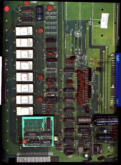
Variant of Pac1 / Pac2
Notable items of this board.
- Unique Sync Buss Controller Board (brighter green sub board near bottom).
- Nine (9) Dip Switches.
- 2 Sets of Coin Counter Transistors.
- Eight 2716 format EPROMs in Row 6.
- Unstuffed Power Supply section, as this board is jumpered to accept DC voltage (+5, +12 VDC).
This board must mate with the left half of the Pac1 / Pac 2 ( Pac 2 PCB). I'm only showing the unique half here.
This particular board is from Europe - Thanks to James G Watt for the scan (Former website located at www.kinetic-arts.demon.co.uk).
Rock-Ola (Eyes) Bootleg
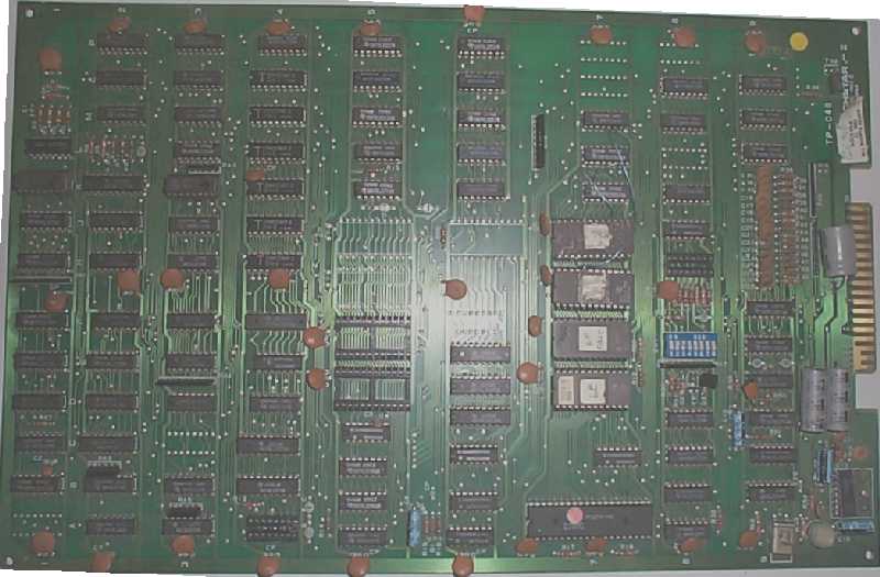
(Techstar - III)
Notable items of this board
- Data lines D3 & D5 are swapped (requires unique ROM set).
- 3 Rows of Rom 5, 6, & 7. (Row 6 is unused in my example).
- Same pinouts as PAC-3.
My particular board is marked "TP-048, TECHSTAR-III, Miami 1982, Made in Japan" in Silkscreen. There is a paper sticker obscuring the silk screen print. On the paper sticker is printed "Rock-Ola C 1982 All Rights Reserved". The paper sticker is also marked by hand "C6390-A". The 2 sockets in row 5 should be filled with Maze/Charater ROMs. Also this board has ROMs stacked in the 7H, 7J locations & wiring to hack this board to run as a Ms Pac-Man (bootleg).
GDP-01 (Japan?)
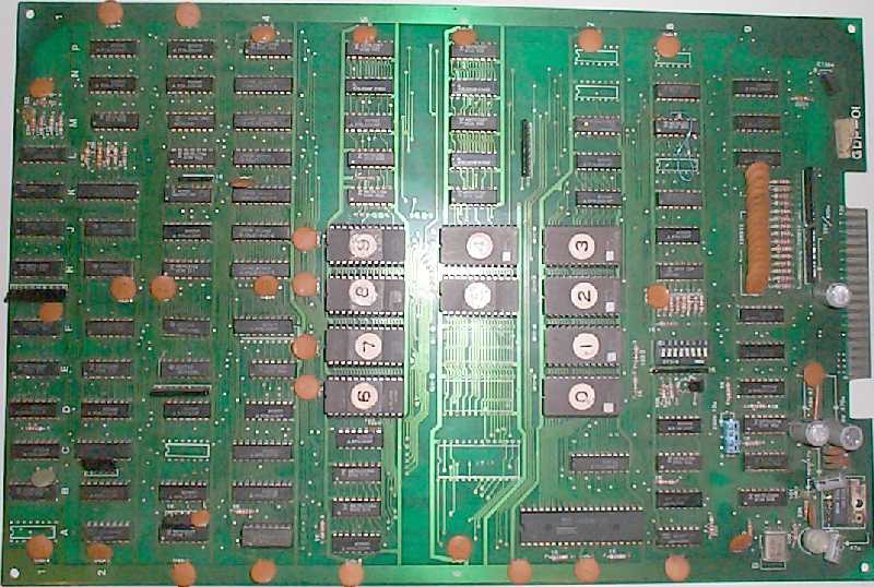
Notable items of this board
- 28 pin socket laid out above & to the left of the Z80. The pinouts appear to match the Sync Buss Controller chip/piggyback although this socket is not used.
- Data lines D3 & D5 are swapped (requires unique ROM set).
- 3 Rows of ROM 5, 6, & 7.
- Same pinouts as PAC -3.
- Has 3 wires for the chips select on ROMs 4 & 5 like the common Ms Pac bootleg hack.
My particular board has no markings other than "GDP-01" & Asian text inside of 28 pin socket above Z80.
Variation of this board will use a piggyback board marked "GDP-02" which has a flying wire from main board 8B pin 11 to GDP-02 IC 4 pin 12. This board may be replaced by a Sync Bus Controller board (without the flying wire). I assume boards equipped with GDP-02 run non bootleg style software.
Sega Bootleg Pac-Man
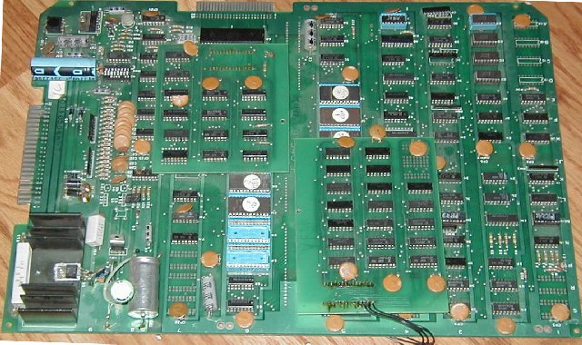
I've seen a one of these boards & have recieved pictures of 2 different boards. On board did not have AC power supply section & had custom ICs (Namco?) at 5S & 6D. The above board has unusual replacement boards for the custom ICs & has the AC power supply section stuffed. It isn't visible in the picture but the board has "SEGA" in the copper trace, next to 5E/5F ROMs.
Bootleg Pac-Man #1
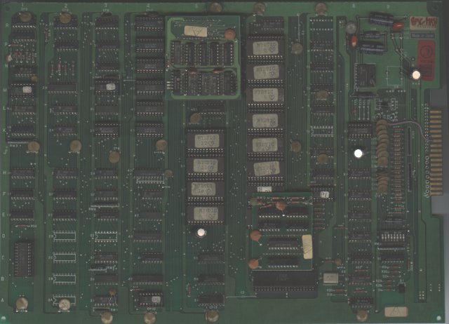
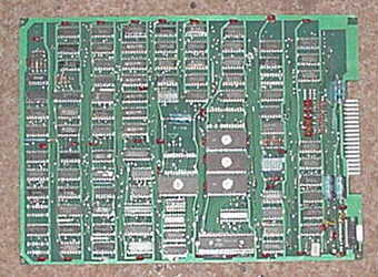
I appologize for the picture quality, this is all I have of this board and am GUESSING it is a Pac-Man. The most unusual feature of this board is the Screen RAM in the lower left corner, a single chip turned perpendicular to the other chips (ala Galaxian). If anyone has one of these boards please e-mail me!
Bootleg Pac-Man #2
Notable items of this board....
- Uses 2764 format eproms.
Bootleg Pac-Man JAMMA #1
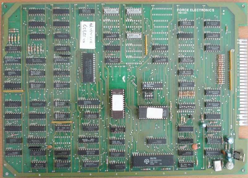
2 Versions of this board have surfaced. One was marked "Made in Greece", which was found in Spain. The above board is marked "FORCE ELECTRONICS" and is actually running Zola Gal software. Notice the 4 dip switches above the ROM in the center of the board. Zola Gal plays a time based game & these dips are for the time parameters.
Bootleg Pac-Man JAMMA #2
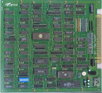
This board has a couple custom of PAL chips. I've heard complaints that this board "seems" / "feels" / "sounds" a bit off in terms of play but I've yet to do a double blind test.
Bootleg Pac-Man JAMMA #3
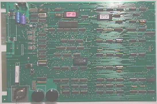
Two-Bit Score made these. The newest version has 2 edge connectors and may plug in either a JAMMA or ORIGINAL PAC-MAN harness. Appears to have SRAM & other software upgrades. This board is no longer available due to copyright concerns.
Bootleg Pac-Man on Galaxian Hardware
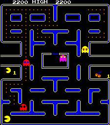
A port of Pac-Man to Galaxian's hardware exist. This software must be of bootleg origin as it is commonly seen on a bootleg system board closely based on Galaxians hardware. Notice that the colors are different as is the screen proportions, Credit, Level & Lives remaining are incoporated in the Maze section (look at the middle exits). The sound is also quite a bit different.
Pictures of the bootleg Galaxian Style board were originally located at surf.to/joystick by BrianPipa and look under his Pac-Man link. Notice that this board uses a "cartridge" approach to software swapping. This system also runs a few other games, all bootleg versions of orignal games such as Moon Cresta & The End to name a few.
There is also documentation on the web how to convert a Original Galaxian PCB to run the bootleg "galxian version of Pac-Man" software. At one time you were able to find that information at www.amug.org/~necro/video/
Rumor Mill: Scud Storm
I had one former route operator email me and tell me about a custom homebrew called Scud Storm made in the 90's around the time of the Gulf War. It replaced the ghosts with jeeps mounted with scud missiles and the fruit bonuses were weapons like grenades.
I have no source of truth behind this, but sounds interesting. Hoping to see screenshots for this Ms. Pac-man bootleg.
Bootleg Ms. Pac-man #1
Photos of what is believed to be a Bootleg Ms. Pac-man, possibly "Come-Cocos", that were submitted from a collector in France. If "Come-Cocos", this bootleg would have been released by Cocamatic in 1992. The components on this board look to be laid out similarly to Bootleg Pac-man Jamma #1. If you have any other information to better fill out this description, please contact me.
Crazy OTTO
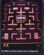
Picture from TIME magazine. "Let me tell you a story.
I worked for the original Midway Games part time from 1975 through 1979, and full time from 1980 through 1988 until they were bought by Williams.
I worked part time as technician, and full time as an Electrical Engineer.
At one point during the production of Pacman (1981?) someone brought
us a game named Crazy Otto to look at. It had a character with legs that
would
chase the monsters. It also had a new set of mazes. They had reversed
engineered Pacman and updated it. We thought about suing them.
Somebody had the idea (I don't remember who) to make the main character
female. One of our artist sketched a red bow onto the head of pacman. The
images were changed, and thus MS Pacman was born.
Instead of suing the company, we entered into a licensing agreement
with them. The company who did Crazy Otto was General Computing Corporation,
located somewhere in Massachusetts.
I believe that we phased Pacman out of production somewhere after 90K games and replaced it with Ms Pacman.
I do not know where to find copies of the original Crazy Otto roms.
Regards, Cary"
-From MSNBC report
Midway was actually slow adopting a sequel to Pac-Man. In 1981, MIT students Doug MaCrae and Kevin Curran approached Midway president David Marofske with a PAL board that converted Pac-Man into Crazy Otto, basically Pac-Man with legs. Since he did not have a sequel for Pac-Man, Marofske proposed tinkering with Crazy Otto and using it as a sequel. The final result was Ms. Pac-Man. Midway sold over 119,000 copies of Ms. Pac-Man, making it the most popular game in U.S. arcade history.
(Thanks Nathan)
Bootleg Power Supply Adapter
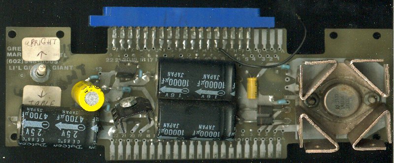
Made by Greenbriar Marketing Intl (602) 948 0005. Marked as "Li'l Green Giant". This adapter is designed to plug into an original Pac-Man wiring harness and convert the AC voltage to DC voltages. The board has provisions for -5 VDC (7095), +12 VDC (7812) and +5 VDC (LM323K). The particular unit show above was customized to adapt an original Pac-Man harness to a PAC-3 bootleg Pac-Man board.
Projects....
Currently seeking help on these projects.....
- Jr Pac Man hack on a Pac Man PCB. I have parts to the board thanks to Mike Ranger!
- Ponopoko software on a Pac PCB.
- The Glob software on a Pac PCB. MAME is running a decryption on the fly method currently.
- Decrypting any epoxy glob cpus (Jumpshot, Shoot the Bull)
Other Parts resources.....
- Appolo Amusements sells Pac-Man (yes Pac-Man !) overlays & other tidbits.
- Arcadeshop.com Sells variety of parts, specialize in cabinet graphics.
- Bob Roberts Sells many edge connectors, fuse block & adapters plus many hard to find eletronic parts, very good guy to deal with.
- Clay Cowgill Sells replacement piggyback boards & some components.
- Marco Specialties Sells the must have manual,"Trouble Shooting Logic Board Part 2". If I didn't cover it, that is because it is in the manual.
- Mark Spaeth Sells adapters, 4 game multigame kits & replacement piggyback boards
- Mayfair Amusements sells Ms Pac Overlays & is soon to stock the monitor glass (Be sure to tell them to add it to the web page!).
- Mike's Arcade Shop sells replacement components, upgrade kits, artwork and has online manuals.
- Musicdistributing.com is repainting/ restoring original yellow Pac-Man cabinets.
- Two Bit Score Sells all parts associated with the game & upgrade chips/conversions. Currently selling an aux board kit to facilitate in repairs.
- Zanen Electronics 806-793-6337 Sells a cap Kit # 920 "The purpose of this kit is to replace the power supply filter capacitors and to help remove hum in the audio."
Additional Troubleshooting, Repair, Restoration Pages
- http://netdirect.net/~astewart/arcade/pacman.html
- http://www.tc.umn.edu/nlhome/g034/johns594/arcade/tech/repairlog.html
- http://www.geocities.com/SiliconValley/Horizon/2253/
-
http://www.mikesarcade.com/arcade - Mike Haaland repair page
- Manual in PDF format
- Troubleshooting Manual in PDF format
- You may want to check out Two Bit Score's web site with their new troubleshooting board & tips.
Star Tech Journal References
Vol 2 #11 Static Kit
Vol 2 #11 Option Switches
Vol 2 #12 Reset Circuit
Vol 3 #1 Ram/Rom Location Code
Vol 3 #1 Degree of Difficulty Mod
Vol 3 #3 Joystick Modifications
Vol 3 #4 Substitute +5VDC Power Transistor
Vol 3 #5 Anti-Static Cleaner Applications
Vol 3 #6 Brightness Adjustment
Vol 3 #9 Coin Door Modification
Vol 3 #9 Glass Display
Vol 3 #10 New Program Available
Vol 4 #2 Ms Pac Man notes
Vol 4 #2 Mini Static Solution
Vol 4 #2 Ms Pac-Man PCB Layout, Difficulty Mods
Vol 4 #4 Wavy Video Mod
Vol 4 #5 Midway Service Notes
Vol 4 #5 Pac-Man troubleshooting steps
Vol 5 #1 Pac-Man Plus Precations
Vol 5 #4 Pac-Man Plus Service Trail
Vol 5 #4 SUPER PAC MAN ENHANCEMENT CHIP????
Vol 5 #6 Ms Pac-Man RFI Modifications
Vol 5 #10 Ms Pac-Man Speed-Up Modifications
Vol 5 #1 Ms Pac-Man Filter PCB cautions, Power Supply Burnt Pins Modification
Vol 7 #9 Jumpshot Option Switches
Vol 8 #1 Jumpshot Reset Notes
Chip Checksums
Super ABC
U1 27010 $F6DD
U14 27040 $1000
U18 82S123 $2A1
4F 82S129 $34F
7F 82S123 $92D
Bucaneer (on PAC3)
1 2732 $FC00
2 2732 $AF00
3 2732 $99DC
4 2732 $26EA
9 2716 $FFEE
10 2716 $64FB
11 2716 $2C26
12 2716 $3B15
Pac-Man (on PAC3)
1 2732 $FC00
2 2732 $B100
3 2732 $9900
4 2732 $429A
9 2716 $E09B
10 2716 $1F25
11 2716 $F45C
12 2716 $58B5
GDP01 Ms Pac-Man
7E $B069
7F $FB98
7H $1C82
7J $FCD7
6E $7A62
6F $E158
6H $FE25
6J $4621
5E $D40E
5F $1565
5H $E82C
5J $52B5
8B pin 11 to GDP-02 IC 4 pin 12
4A $271
7F $73C
GDP ROMs?
6E $2078
6F $DED8
6H $AC68
6J $FE44
Ms Pac Boot 6
2716 format = $F9B2
All screen shots were captured with the use of the MAME emulator (V.24) or AGE.
Photograph of Driving Force PCB provide by James Marous http://www.erinet.com/jamesm
